
The title might suggest that I’ll be discussing the dangers of television content, but my focus is actually on the physical hazards associated with televisions in the past — specifically, the risks involved in the manufacturing of certain TV components, with particular attention to flat shadow masks.
Shadow-masks: how the tiny grid behind colour CRTs was made — and a brief look at Philips FSM in Sittard
For most of the late 20th century, the color picture tube’s secret hero was the shadow-mask: a thin metal sheet, densely perforated with microscopic holes or slits, positioned just behind the display’s glass to ensure each of the three electron beams excites only the intended red, green or blue phosphor element. Making these masks was a demanding precision micro-manufacturing process: the parts had to be extremely flat, have uniform hole geometry across large areas, resist heat and mechanical stress, and be produced at very high volume and repeatable quality.
Materials and the basic idea
Shadow-masks were typically made from steel alloys (including low-expansion alloys such as Invar for high-precision applications) in thicknesses often measured in fractions of a millimetre. The combination of material selection and mask geometry controlled thermal expansion, mechanical stiffness, and how the apertures shaped the electron beams. The mask’s performance is a system trade-off: smaller holes and tighter tolerances improve color purity and convergence but make manufacturing harder and can reduce brightness.
The Manufacturing of Shadow Masks
With Technical Detail, Safety Considerations, and Chemical Process Information
(Including context for Philips FSM – Sittard)
- Introduction
Shadow masks were an essential component in colour cathode-ray tube (CRT) displays. They are extremely thin metal sheets, perforated with hundreds of thousands of microscopic holes or slits. These apertures ensure that the electron beams inside the CRT only strike the correct red, green, or blue phosphor dots on the screen.
The process of manufacturing shadow masks combines metallurgy, photolithography, and chemical etching — forming one of the most complex mass-production methods in the display industry. The Philips FSM (Flat Shadow Mask) plant in Sittard, the Netherlands, was one of the facilities that specialised in this technology, particularly during the late 1980s and 1990s.
- Material Selection and Preparation
2.1 Base Materials
Shadow masks were typically made from steel, nickel, or Invar (a nickel–iron alloy with very low thermal expansion). Invar was preferred for high-performance displays because it reduced distortion caused by heating during CRT operation.
The metal sheets used were only about 0.1 to 0.2 mm thick — thinner than a human fingernail — and had to be perfectly flat, smooth, and free of internal stress.
2.2 Cleaning and Preparation
Before any patterning could begin, the raw sheet was chemically cleaned to remove oil, grease, oxides, and rolling residues. Common cleaning steps included:
Alkaline or detergent degreasing
Acid pickling (often with hydrochloric or sulfuric acid)
Rinsing in deionised water
Drying in clean, filtered air
This surface preparation ensured strong adhesion of the photoresist used in later stages.
- Photolithographic Patterning
3.1 Applying Photoresist
A photosensitive resist (similar to those used in microelectronics) was applied to one or both sides of the sheet, either by roller coating or as a dry film. The resist was then baked to harden it slightly.
3.2 Exposure
A photomask — a high-precision glass template containing the shadow mask hole pattern — was placed over the resist. The resist was then exposed to ultraviolet light.
Each side of the metal sheet was exposed separately, usually with slightly different hole sizes on each side. This controlled the taper of the holes through the metal’s thickness, allowing better electron-beam convergence in the final CRT.
3.3 Developing the Pattern
After exposure, the resist was developed in an alkaline solution, washing away either the exposed or unexposed areas (depending on resist type).
The remaining resist protected the metal where no etching was to occur.
- Chemical Etching
The heart of the process is photochemical machining (PCM), or chemical milling.
The patterned metal sheet was placed in an etching chamber or spray etching machine.
Etchant solution was sprayed or circulated across both sides of the metal sheet.
The unprotected areas were dissolved by the etchant, creating thousands of precisely shaped holes.
Careful control of etch rate, temperature, and flow velocity ensured uniform hole size across the entire sheet.
For the highest precision, etching was performed simultaneously from both sides. When the etch fronts met, they formed the final aperture shape with a controlled taper.
Common Etchants
For steel and Invar, typical etchants included:
Ferric chloride (FeCl₃)
Nitric acid (HNO₃)
Hydrochloric acid (HCl)
Cupric chloride (CuCl₂) (occasionally used for nickel alloys)
Etchants were maintained under strict pH, temperature, and oxidation-reduction potential (ORP) control to achieve consistent results.
After etching, the photoresist was stripped away in an alkaline or solvent bath, and the sheet was rinsed and neutralised.
- Post-Etch Treatment and Finishing
Once etched, the mask required further processing to improve mechanical and optical properties.
5.1 Stress Relief
The thin sheet was heat-treated (annealed) to relieve internal stresses from rolling and etching. This prevented distortion during forming and operation.
5.2 Surface Treatments
Various coatings were applied to reduce reflections and improve durability:
Black oxide coating – reduced light reflection inside the CRT
Nickel or tin plating – improved corrosion resistance
Chromate passivation – enhanced stability and cleanliness
5.3 Forming and Framing
Depending on the design, the mask was either kept flat or formed into a slightly curved shape. It was then attached to a metal frame under tension.
In “flat shadow mask” CRTs — such as those developed by Philips FSM in Sittard — this forming process demanded especially tight tolerances to maintain uniform flatness across the screen area.
- Inspection and Quality Control
Every mask was subjected to rigorous inspection:
Optical measurement of aperture size and pitch
Checking taper profile and bridge width
Mechanical testing for flatness, warpage, and residual stress
Surface inspection under microscopes for pinholes or cracks
Because each mask contained up to a million holes, even microscopic defects could cause display artefacts. This required high-precision metrology and statistical process control (SPC) — something Philips FSM was known to pioneer in its quality systems.
- Safety and Hazard Considerations
7.1 Sharpness and Physical Hazards
Even though photochemical machining produces burr-free edges, the remaining structures are razor-sharp at the microscopic level.
Hazards included:
Cuts and lacerations during manual handling
Fragmentation — fine bridges could crack, creating tiny sharp fragments
Spring-back injuries during forming or tensioning operations
Operators were required to wear cut-resistant gloves, protective sleeves, and eye protection, and masks were usually handled with specialised tools to avoid direct contact.
7.2 Chemical Hazards
The process used numerous corrosive and toxic chemicals, including acids, alkalis, and metal salts. Typical hazards:
Ferric chloride – corrosive, stains skin, produces toxic fumes when hot
Nitric acid – oxidising, causes severe burns
Hydrochloric acid – strong acid, harmful vapour
Sodium hydroxide – caustic, used in resist stripping and neutralisation
Chromate solutions – toxic, carcinogenic (historically used in passivation)
Proper ventilation, fume extraction, neutralisation tanks, and waste-treatment systems were mandatory. Workers required chemical-resistant gloves, aprons, and respiratory protection where needed.
7.3 Waste Treatment
Etching produces large volumes of spent acid and dissolved metal salts. These were treated using:
Neutralisation with alkalis
Precipitation of metal hydroxides
Filtration and disposal according to environmental standards
Philips and other major display manufacturers were among the first in Europe to implement closed-loop acid regeneration to reduce environmental impact.
- The Philips FSM Facility in Sittard

The Philips FSM (Flat Shadow Mask) facility in Sittard, the Netherlands, was part of Philips Display Components. It specialised in flat mask technology for high-resolution CRTs and computer monitors.
Engineers at the Sittard site focused on:
Optimising the photochemical etching process
Reducing mask warpage (“doming”)
Implementing Statistical Process Control (SPC) and Failure Mode and Effects Analysis (FMEA)
Maintaining high yield for mass production
The FSM plant played a crucial role in Philips’ efforts to produce flatter, brighter, and more stable CRT displays before the industry’s shift to flat-panel technologies in the 2000s.
Philips operated multiple manufacturing units across the Netherlands and Europe for tube and display components. Publicly available résumés, local histories and period reports reference a Philips unit in Sittard that worked on “FSM” — commonly expanded in these sources as Flat Shadow Masks or related flat mask/division activities — and indicate that the Sittard site included a flat shadow-mask department and related process engineering roles during the late 1980s and 1990s. Those sources describe responsibilities such as process optimization, SPC (statistical process control) roll-out, FMEA/risk management, and quality engineering for high-volume mask production lines — the kinds of activities you’d expect at a shadow-mask manufacturing plant striving for high yield and tight tolerances.
Local press and regional history pieces also document Philips’ broader industrial presence in Limburg (including Sittard) and the company’s shifting footprint over decades, which affected plants and activities there. That context helps explain why specialized manufacturing activities (like FSM) were located in regional Philips plants where vacuum-tube and display manufacturing knowledge concentrated.
Why this mattered — and why it largely disappeared
Shadow-masks were essential to CRT color quality; better masks made better pictures. However, the entire class of components declined rapidly as flat-panel technologies (LCD, then OLED) replaced CRTs. By the late 1990s and 2000s demand collapsed and many specialist lines — including flat shadow-mask production — were wound down, repurposed, or closed. The process knowledge remains a notable chapter in precision chemical machining and high-volume microfabrication history.
I worked for 10 years at Philips FSM, spending the first 5 years in product inspection and the last 5 years in the chemical facilities department for FSM. In this role, my colleagues and I were responsible for all chemicals used in production, including their testing, handling, and disposal.
I was also a member of the disaster recovery team, which collaborated closely with the company fire department. As part of this role, I was trained to operate in a hazmat suit, similar to the one shown below.

Fortunately, we were never called out.
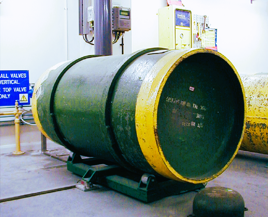
The reason for the training was that one of the chemicals we used was chlorine. Each day, about 8,000 liters of chlorine were used in production, delivered in rigorously tested tanks like the one shown below. Despite the strict safety measures, if one of these tanks were to explode or leak, it could potentially devastate an entire small town—hence the critical role of the disaster recovery team.
This illustrates that making TVs at that time could lead not only to cuts and chemical poisoning, but in extreme cases, even the destruction of communities.
So, as you can see, the title “The Dangers of TV” is quite appropriate—not just because of what we watch, but because of the very real physical hazards involved in making televisions in the past.
sources
https://en.wikipedia.org/wiki/Shadow_mask
https://patents.google.com/patent/US3973965A/en

Leave a comment